A while ago someone asked what would be the best a/c transformer to use for a US 115V system and the thought crossed my mind that answer was probably a European 230V version. The rational being that a 230V device connected to a 115V supply would be much further from saturation than a normal 115V transformer and therefore there would suffer much less distortion.
This set me wondering if there was a small 400V transformer that would do the same thing for a 220V supply but I couldn't find such a device. However, the obvious alternative is to connect 2 small 230V transformers in series in order to achieve the same effect.
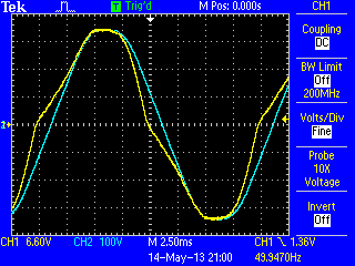
I happen to have a few Wylex MTS8/1 DIN rail mounting bell transformers that I intended to use for my 3-phase monitor but the distortion was so bad that I abandoned the idea. You can see why in this screen shot...

The blue trace is the raw 240V supply and the yellow trace is the low voltage output. The transformer is clearly heavily into core saturation and the device also makes a loud buzz and consumes 4W of power with no load.
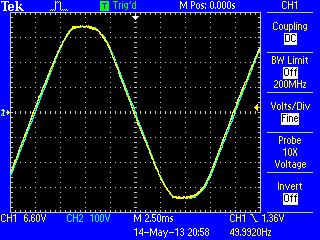
With two of the devices in series, primary and secondary, we get a much better result...

There is now no obvious distortion but perhaps just a tiny amount of phase shift. The two transformers setup is also silent and only consumes 2W.
So it seems that rather than using one, large, over specified transformer it may make more sense to use two tiny transformers connected in series.
Re: Using 2 transformers to improve voltage signal quality
I'm not surprised it buzzes with that much saturation visible!
You might like to try with the secondaries in parallel, which will ensure they share the primary voltage more equally. Robin tried this a long while ago but didn't see an appreciable improvement. Jörg uses 440 V Hahn transformers at 230 V and while there is still some phase shift, the variation with voltage is much reduced. Clearly, this is something that is not guaranteed but like everything else varies from manufacturer to manufacturer and design to design.
I assume you don't have the facilities to check over the full range of input voltage? You can get an accurate measure of phase shift using the 'scope in X-Y mode.
Re: Using 2 transformers to improve voltage signal quality
Yes, I tried this trick a while ago with two identical AC adapters. I only connected the two primary windings in series, and then just used one of the secondaries. The technique didn't seem to work well for me, so I adandoned the idea. Your display, Martin, looks remarkably good.
Maybe connecting the two secondaries together is important. For the tiny amount of current that is being taken, I didn't think that it would be make any difference.
Re: Using 2 transformers to improve voltage signal quality
I just checked and there is a slight difference in primary voltages - 127 & 120 volts, and yes you are right Robert (as usual!) that connecting the secondaries in parallel equalises the voltages. It also produces a similar waveform to the series case, but obviously at half the voltage..
With the secondaries not connected at all there is distortion on both of them, although different, presumably due to slightly different inductances?
I don't have a Variac but I do have an auto transformer with quite a few steps so I'll dig that out at some point. However, I'm inclined to think that there won't be much variation in phase shift over the range of possible supply voltage. As I said before, I think most of the phase shift you saw on the adaptor tests is really distortion which isn't present when using two transformers. Even in my first picture above I don't believe there is much phase shift, just loads of distortion around the zero crossings. The peaks are still pretty much aligned.
Re: Using 2 transformers to improve voltage signal quality
I've had a shot at measuring phase shift in X-Y mode but as the variation over the range 220-270V only seems to be a few tenths of a degree I'm finding it quite difficult to measure it accurately. All I'm doing is taking the ratio of the width to the height of the Lissajous figure and multiplying by 90. The result is 4.5 +/- a few tenths over the range. Am I missing a trick here?
Those 440V Hahn transformers look ideal. I see they do a very small 0.5VA range. One of those inside a plug-top case together with a 240V to 3V SM PSU would make an ideal dual function supply for emonTx.
Re: Using 2 transformers to improve voltage signal quality
"Am I missing a trick here?"
You could be....
The phase shift is ψ = sin-1 (X2/X1) = sin-1 (Y2/Y1) where X1, Y1 are the overall width/height of the ellipse and X2, Y2 are the width/height of the ellipse at the middle/zero crossing. You can of course change scale to zoom in on the middle to measure more accurately..
(That is one of Jörg's transformers at 253 V).
Re: Using 2 transformers to improve voltage signal quality
Thanks for that Robert. I probably should have thought about it a bit more but since my X and Y scales were the same and the phase shift is small so sin(x)~=x the results were about right anyway.
It's still a bit of a faff to do though so I decided to use my phasecal sketch instead. Just a slight mod to convert CT2 to a high voltage input and it will measure phase shift directly - you don't even need a scope.
Spot results are:
225V 3.8°, 250V 4.0°, 270V 4.2°
Re: Using 2 transformers to improve voltage signal quality
Oh, and Jörg, if you're listening, do you have a source for those Hahn transformers? Thanks.