I've been toying with the idea of modifying an emonTx to provide 2 current ranges in order to improve the resolution at low currents while still maintaining the ability to measure 100A. I don't want to use any hardware range switching as it will probably require a settling time, so I'm considering using 2 burden resistors in series. Like this...
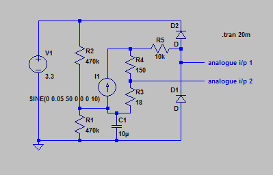
R3 is the normal 18 Ohm burden resistor and will provide a range of 0-100A on analogue input 2. R4 is an extra burden resistor which will give a range of about 0-10A on analogue input 1. When the current exceeds this range analogue input 1 will clip at the supply rails and R5 will absorb the excess voltage with only a very small affect on analogue input 2. I'm assuming D1 and D2 are the protection diodes in the ATMega so this circuit only requires 2 extra resistors above the normal input circuit.
It should be fairly simple to implement auto-ranging in software.
Can anyone see any issues with this idea? (I've attached the LTspice file if anyone else wants to play with it)
Re: dual-range CT circuit
When you increase the burden resistance, you are overloading the c.t. (remember, it works in a constant current world, you are used to thinking in the constant voltage world).
I didn't do a full set of measurements on the c.t. with a burden that high. At 60 A primary current and 116 Ω burden, total distortion was 5% (about half of that due to the flat top of the mains voltage here), and at 40 A the same distortion was got with 209 Ω burden. So without doing more tests, I can safely say you'll have a distorted current wave. But above 5% total, distortion increased much more rapidly.
Re: dual-range CT circuit
Mmm, non-starter then. I did have a quick look at your graph in the CT test building block but for some reason I had the X axis as secondary current in milliamps even though you've clearly labeled it as primary current - duh!
Re: dual-range CT circuit
Why not a log amp?
Re: dual-range CT circuit
I really must sit down one day and build a Spice model of that c.t!
I'm privileged, I've got the raw data from those measurements. I can run some more tests, but the limiting factors will be waveform distortion and phase shift as it approaches saturation, and the real question is how much distortion is acceptable. Taken to the extreme, you can see what happens in the 'scope pictures. I've got 39 Ω as the burden that gives 5% distortion at 100 A, and that would give you a 2 x advantage. Personally, on a purely engineering basis, I don't think that's worth the trouble.
I think a switched gain amplifier as Atmel prototyped is the best hope (and I think collectively they know a bit about designing circuits). Glyn has got a working prototype but I think it's gone on the back burner.
Re: dual-range CT circuit
Brian D: "Why not a log amp?"
Then what happens at the zero crossings? Rectification is out because you need to preserve the phase relationship to know the direction of power flow.
Re: dual-range CT circuit
A log amp would also be an issue for the software as you'd have to match the log scale when scaling to real current/power.
How about a little daughter board with amps with a fixed gain of 10. It could plug onto the emonTx headers, pick up the CT1 & CT2 analogue inputs and feed the x10 signals into the 2 unused analogue pins. Since it wouldn't require any changes to the emonTx board it could be an optional extra in the shop.
Re: dual-range CT circuit
How about a little daughter board with amps with a fixed gain of 10. It could plug onto the emonTx headers, pick up the CT1 & CT2 analogue inputs and feed the x10 signals into the 2 unused analogue pins. Since it wouldn't require any changes to the emonTx board it could be an optional extra in the shop.
That sounds like a much better idea. However, at very low power my house load is probably mostly switch mode PSU's. The current waveform is not at all sinusoidal and the phase relationship is poor so will your improved resolution be very much use to you?
Re: dual-range CT circuit
However, at very low power my house load is probably mostly switch mode PSU's. The current waveform is not at all sinusoidal and the phase relationship is poor so will your improved resolution be very much use to you?
Provided you're using a monitor that also measures V and calculates real power, I think it will be. Personally, I think tuning my baseload is one of the most useful things I can do with an energy monitor. I'm unlikely to use my oven less often just because I now know how much power it uses. But having discovered how much power my subwoofer uses in standby, I do now turn it off at the wall. Sure the 20W is vulnerable to chants of "micropence pedant", but run it 24x7 for a year, and it adds up.
I recently posted some data here: http://openenergymonitor.org/emon/node/2296 on nasty current waveforms. My spreadsheet experiments suggested that even at relatively low sampling rates of say 50 (I,V) samples per mains cycle, you can still get pretty close to real power measurements.
Re: dual-range CT circuit
There's nothing inherent in the c.t. that stops it measuring down to nothing. Lack of screening on the secondary and the cable connections could result in pickup that would need careful handling, as would the problem of digital noise getting into the amplifier. But provided the phase shifts in both c.t and v.t. are corrected properly, then measuring real power should not be a problem. What I've carefully glossed over there is the slight matter of the two phase shifts not being constant, both depend on the quantity being measured, and not linearly either. So you might need a pair of look-up tables that give a phase correction according to the voltage and current being measured. This is important of course when the power factor is close to zero, a few degrees error here matters a lot more than when the p.f. is close to unity.
For information, from the Atmel AVR1631 App.note: "Energy metering specifications call for accurate measurement of frequency content up to the 20th harmonic which is 1kHz or 1.2kHz depending on the line frequency." Which I find surprising, because a 12/24 pulse thyristor drive can put significant 23rd and 25th harmonic currents into the supply.
Re: dual-range CT circuit
"Energy metering specifications call for accurate measurement of frequency content up to the 20th harmonic which is 1kHz or 1.2kHz depending on the line frequency." Which I find surprising,
Yeh, it does seem low. The "revenue grade" devices I use in my monitor are good for 2kHz bandwidth, or the 40th harmonic.
Re: dual-range CT circuit
Lack of screening on the secondary and the cable connections could result in pickup that would need careful handling
Has anyone done any experiments with regards the location of the burden resistor? I wonder does that have an impact on noise vulnerability.... i.e. a burden resistor inside the CT so you're sending very small voltages down the cable, Vs a burden resistor at the monitor so you're sending very small currents down the cable.
Generally, current loops are considered less noise prone aren't they?
Re: dual-range CT circuit
Has anyone done any experiments with regards the location of the burden resistor?
None that I'm aware of.
Generally, current loops are considered less noise prone aren't they?
That depends on whether the noise is injected as a current or a voltage, and where it is injected! I believe, without a lot of justification and even less proof - apart from experience with microphone circuits etc - that most of the noise is coming into the ADC, either via the analogue supply (which isn't decoupled from the digital supply) or via ground loops - more likely the former.
[A decent microphone amplifier will have a noise input down in the few µV range - to cross two ADC steps you need 100 times that - 300 µV in rough terms.]
If the noise is genuine pick-up from the environment, not carried in the current you're measuring, a balanced front-end amplifier with the burden at the amplifier (and bear in mind by balanced I mean balanced impedances, not necessarily balanced voltages and currents) should help. But if the noise is getting in after the amplifier, it won't help in terms of the absolute value measured by the ADC although it will push your lower limit for measurement down.
So here are the results of a very rough experiment. The c.t. is a YHDC 100 A, no burden, and the cable screen is not connected either end. I plugged it into a microphone amplifier with 30 dB gain (30 x) and a relatively high input impedance, and looked at the output with a soundcard 'scope. This is the green trace. The red trace is a 3 mV rms reference from a signal generator, 50 Hz but not locked to mains (that should give a indicated current of 0.333 A in an emonTx)
1. Pickup from the c.t. No mains cables within 1 m.
2. Holding the c.t. cable in my hand:
3. With the c.t. cable screen earthed at the amp. end (holding the cable made no difference now):